In the previous sections, molecules and ions were depicted using a two-dimensional (2D) Lewis structure. The ease of rendering a structure on a 2D surface has hidden the 3D complexity found in most molecules and ions. Being able to "transform" a 2D rendering into a 3D geometric shape is an essential first step in understanding macroscopic properties such as melting and boiling points, and predicting how molecules react. Although bonding and non-bonding electrons play a role in a molecule's geometry, it is solely the positions of the atoms in a molecule that determine its molecular shape.
VSEPR Theory
Valence Shell Electron-Pair Repulsion Theory enables us to predict the electronic geometry and approximate bond angles around a central atom. The basis of this approach is that
like charges repel.
Electrons are negatively charged and will repel each other. The "exception" to this statement is when two electrons "spin-pair" to form a bond or lone pair . . . one electron's . . . the electron's 4th (spin) quantum number is +½ and the other electron's ms value is –½. However, once a bond (2 spin-paired electrons) has formed, the bond itself is negatively charged. Likewise, a lone electron pair (2 spin-paired non-bonding electrons) is negatively charged. Bonds and lone electron pairs repel one another and position themselves around the central atom in a geometric arrangement that minimizes this repulsion. Once the central atom's electronic geometry is known, its molecular geometry is easily deduced by picturing the molecule with only its atoms.
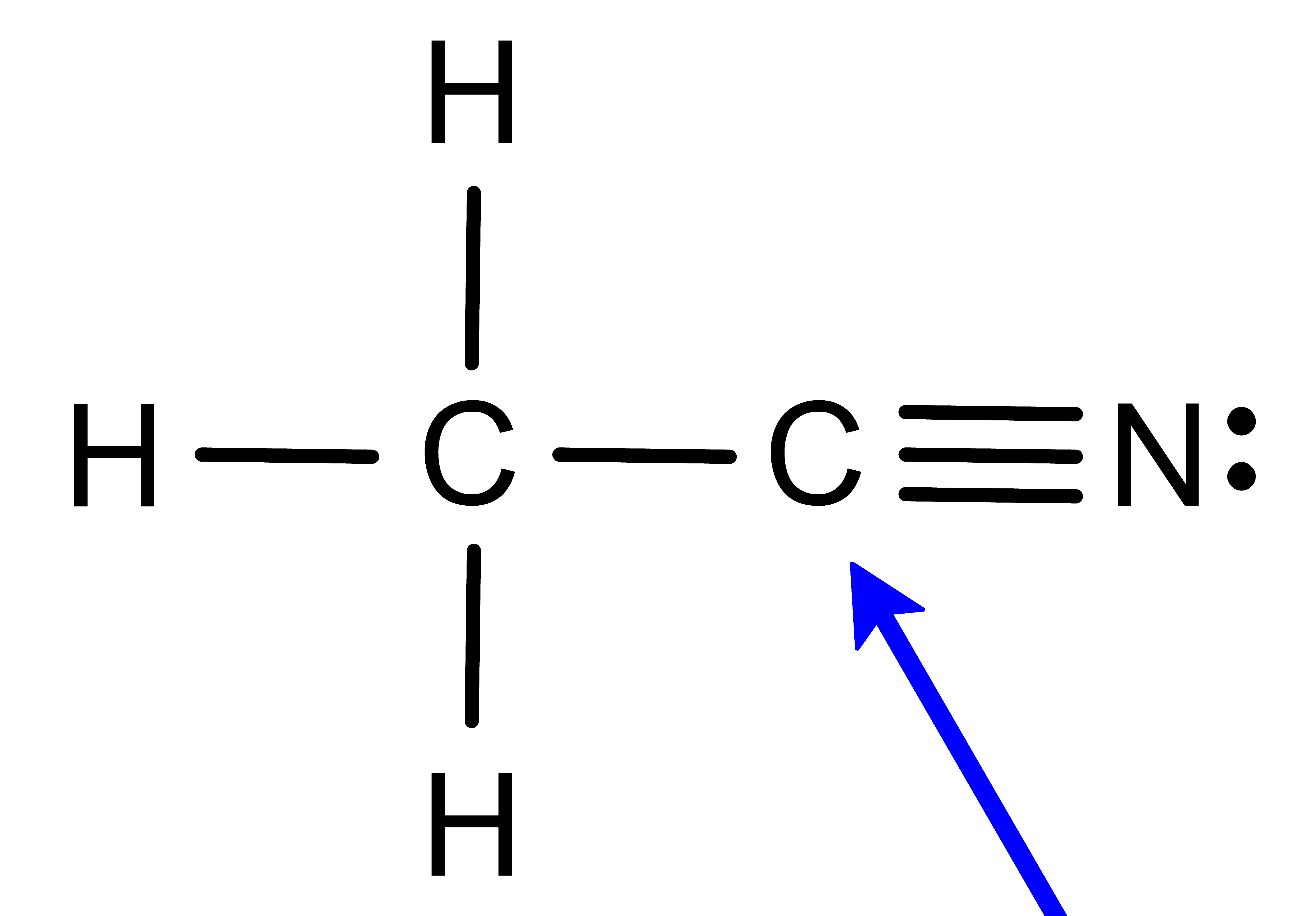
To determine the molecular geometry, we must first use the valence electrons to draw the Lewis structure. From there, the bond type (–, = or ≡) and the number of lone pairs of electrons (:) will reveal the molecule's electronic geometry. Finally, considering only the "centers of mass" provides the molecular geometry.
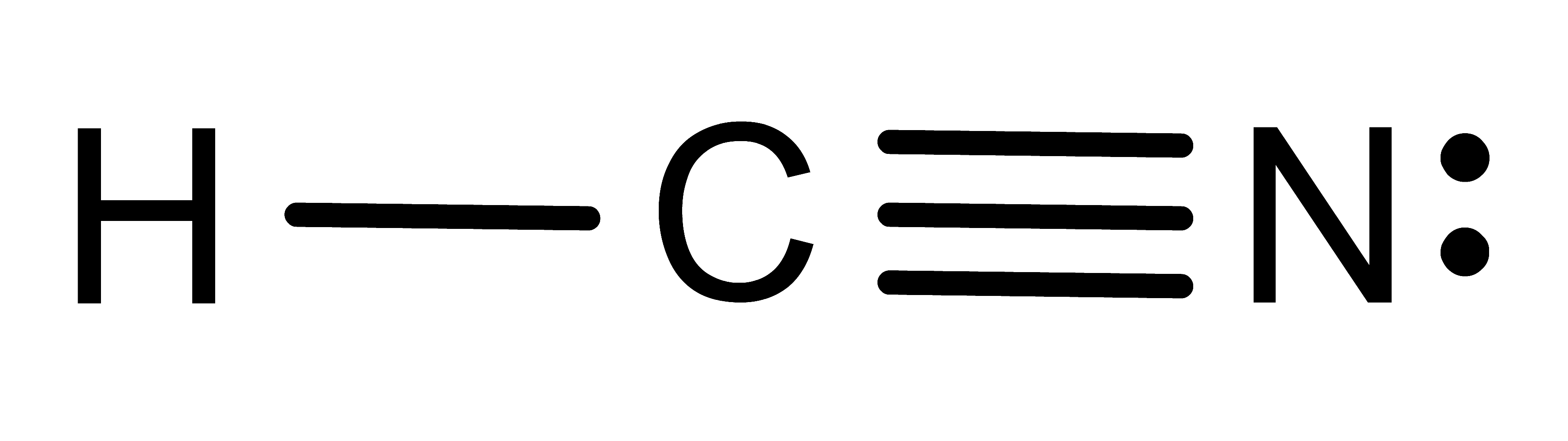
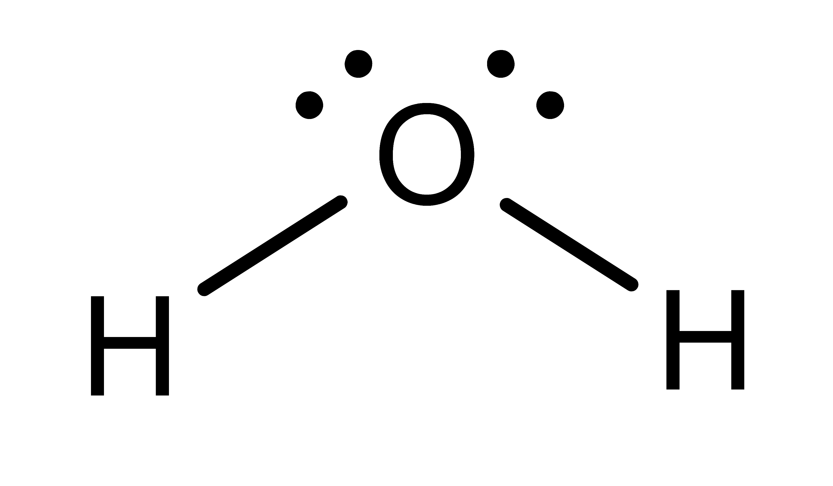
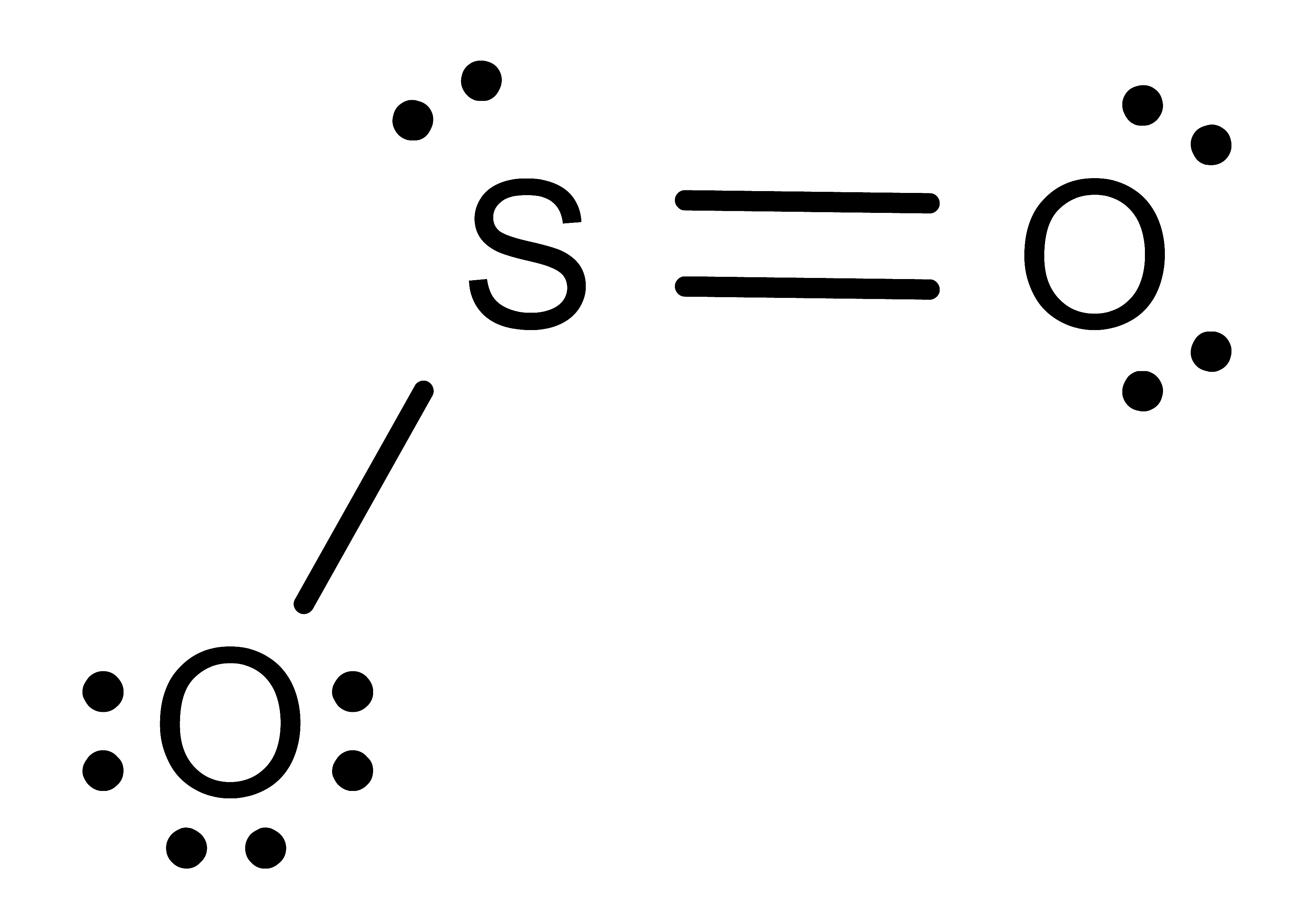
- Determine the number of Electron Domains around the central atom.
- A single bond (–) counts as 1 electron domain
- A double bond (=) counts as 1 electron domain
- A triple bond (≡) counts as 1 electron domain
- A lone pair (:) of electrons counts as 1 electron domain
Activity: determine the number of electronic domains for the central atom in the following molecules. Once you have written down an answer, click Show Answer to check your answer.
Show Answer

Show Answer
Show Answer

Show Answer
Show Answer
Show Answer
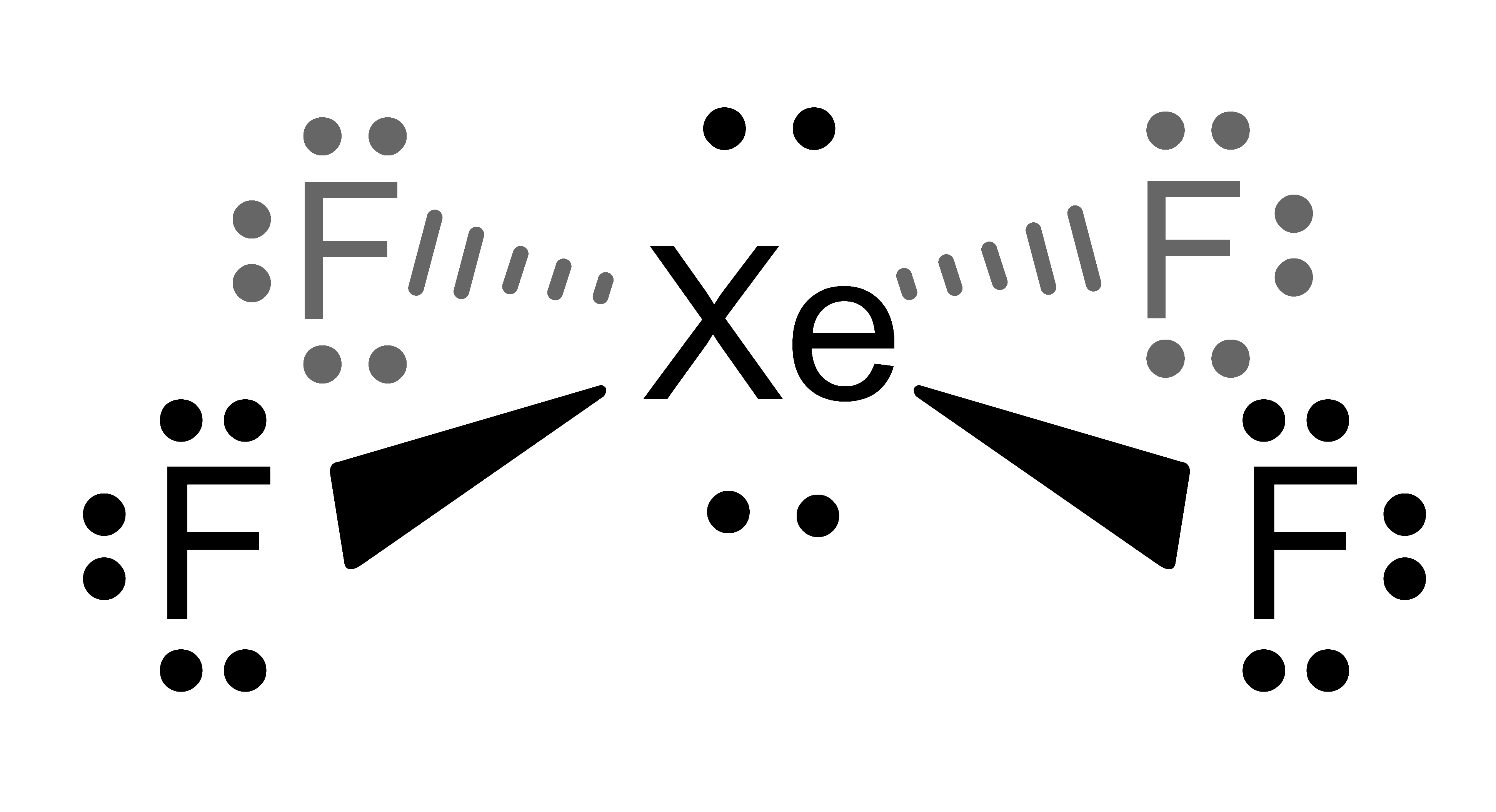
The images in the Activity are drawn with bonds (
 ), dashes (
 ) and wedges (
 ). These 2D drawing enhancements are designed to convey the following 3D meaning . . . .
- denotes that the bond (and both attached atoms) are in the plane created by the computer screen.
- denotes that the bond (and the atom attached at the wider end) are behind the plane created by the computer screen . . . . the atom attached at the other end is in the plane of the computer screen.
- denotes that the bond (and the atom attached at the wider end) are in front of the plane created by the computer screen . . . . the atom attached at the other end is in the plane of the computer screen.
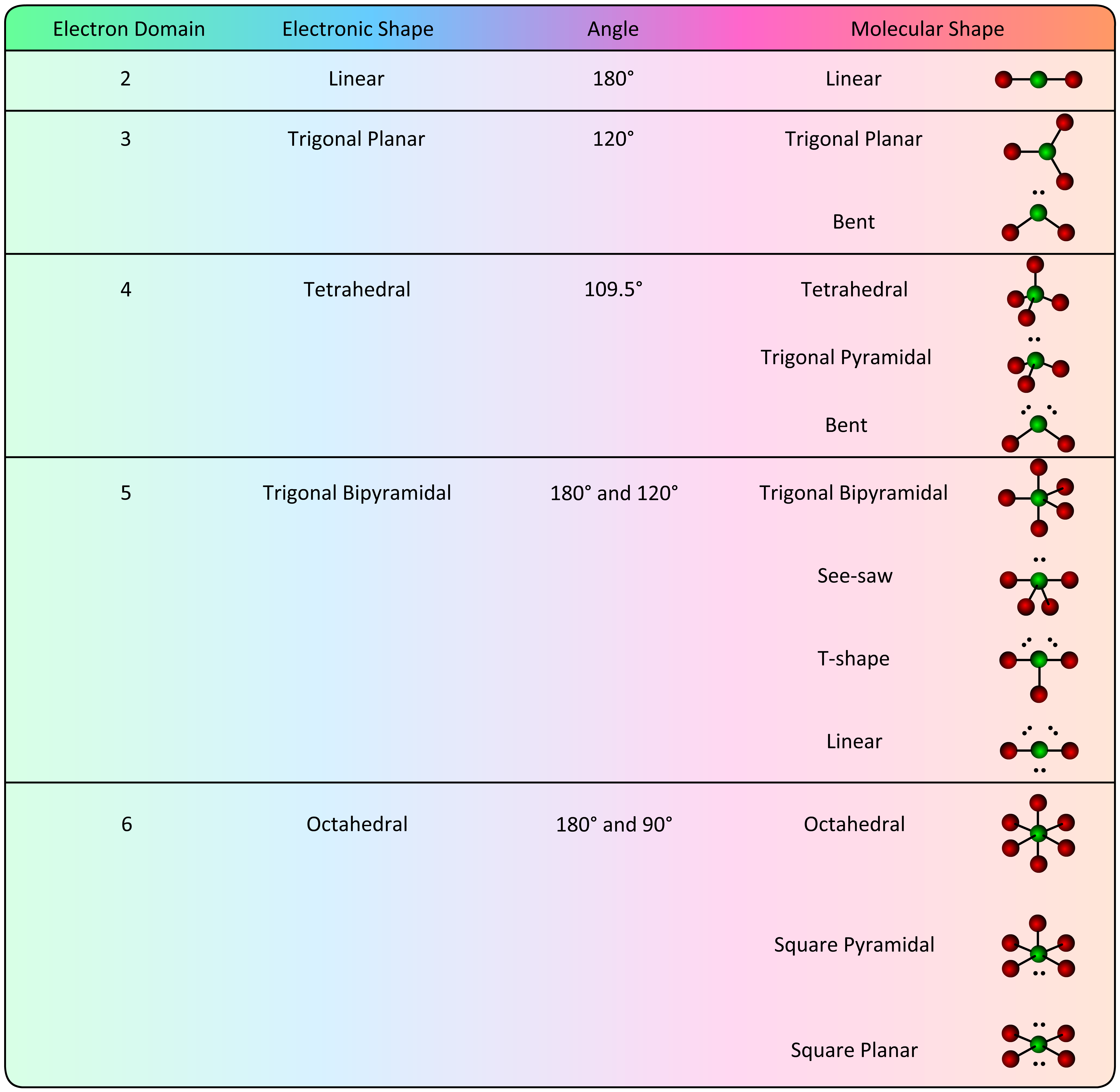
- Determine the Electronic Shape.
- Linear - 2 electron domains
- Trigonal planar - 3 electron domains
- Tetrahedral - 4 electron domains
- Trigonal bipyramidal - 5 electron domains
- Octahedral - 6 electron domains
Activity: determine the electronic geometry for the central atom (or indicated atom) in the following molecules. Once you have written down an answer, click Show Answer to check your answer.
Show Answer
Show Answer
Show Answer

Show Answer
Show Answer
Show Answer
- Determine the Molecular Shape. The electronic shape has positioned bonding electrons (and their attached atoms) at specific geometries around the central atom. To determine the molecular shape, disregard any lone (non-bonding) electrons and consider only the geometry that is created by the central atom and the terminal atoms. The various options are listed in the table below.
The location of the lone electron pair(s) in the See-saw, T-shaped, Linear and Square pyramidal requires explanation. Recall that an orbital is a defined region in space where an electron is likely to be found 95% of the time. Bonding electrons are located in smaller orbitals (spacial regions) because they must be "between" two atoms. Non-bonding electrons are "attached" to only one atom which allows them to reside in a larger orbital. In the trigonal bipyramidal and octahedral electronic geometries, there are two very different orbital locations:
- axial orbitals correspond to the "axis" positions of the Earth
- equatorial orbitals are located at the "equator"
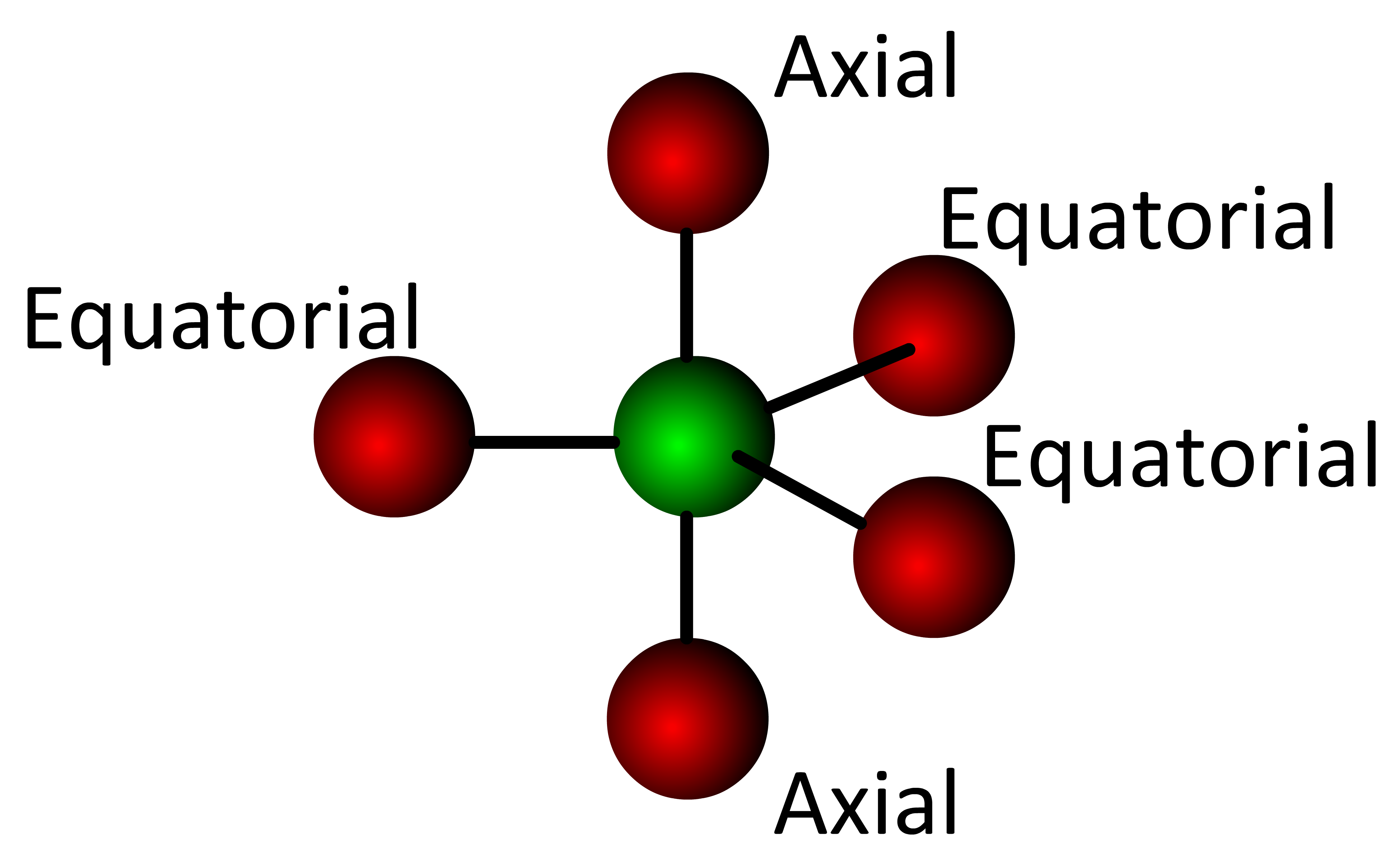
In the trigonal bipyramidal geometry there are two axial positions and three equatorial positions.
The axial orbitals are located at a 90° angle from the equatorial orbitals . . . . each equatorial orbital is located at a 120° angle from its nearest equatorial orbital. Since non-bonding electrons reside in larger orbitals and electronic orbitals repel each other, the most stable location for an electron pair is in an equatorial position (the largest volume of 3D space).
When the Lewis structure of a molecule with a trigonal bipyramidal electronic geometry shows a lone electron pair on the central atom (:SF4), the electron pair must be placed in an equatorial position 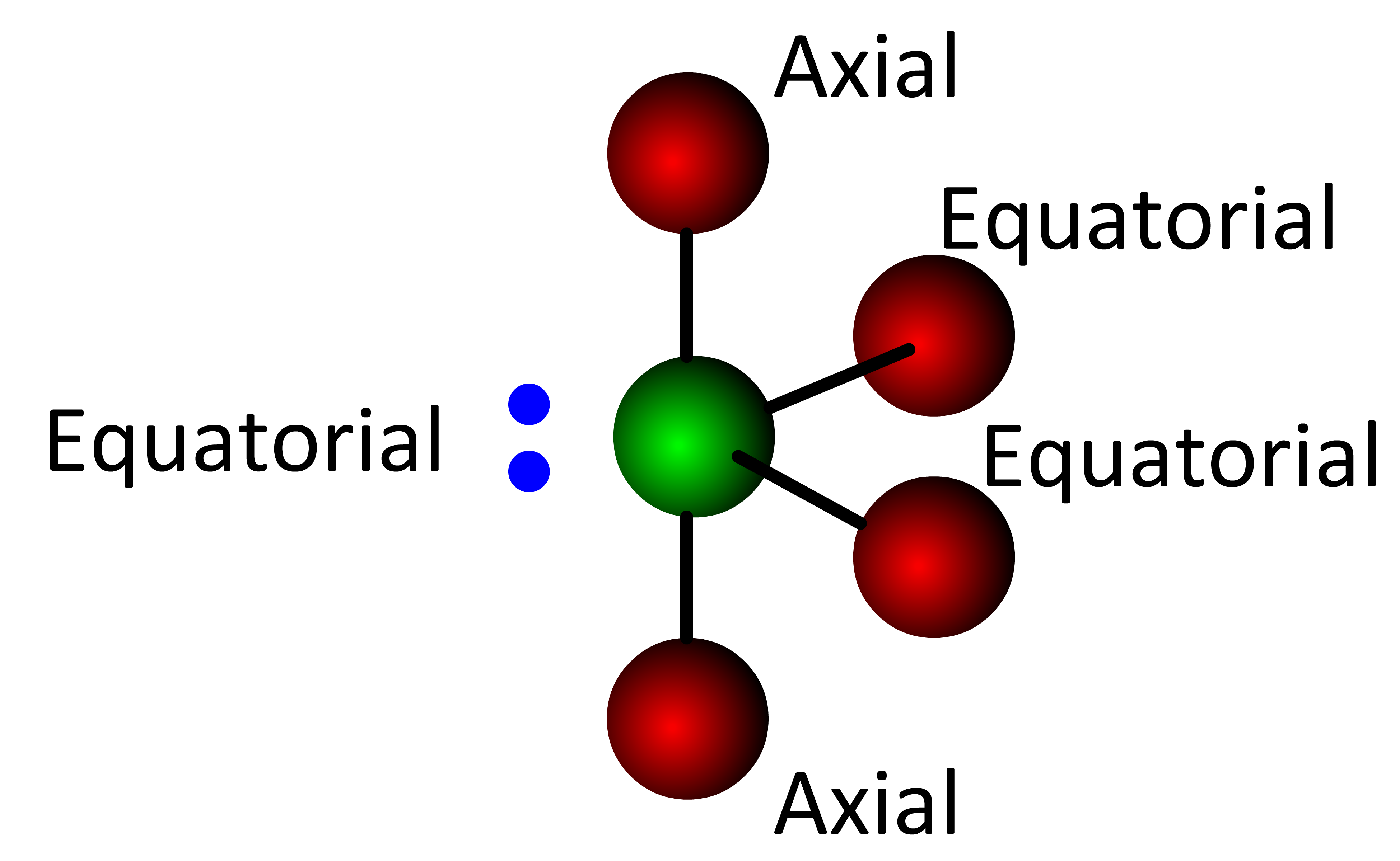 . . . . . this forms the See-saw molecular geometry.
Following this same logic, a second lone electron pair must reside in a different equatorial position 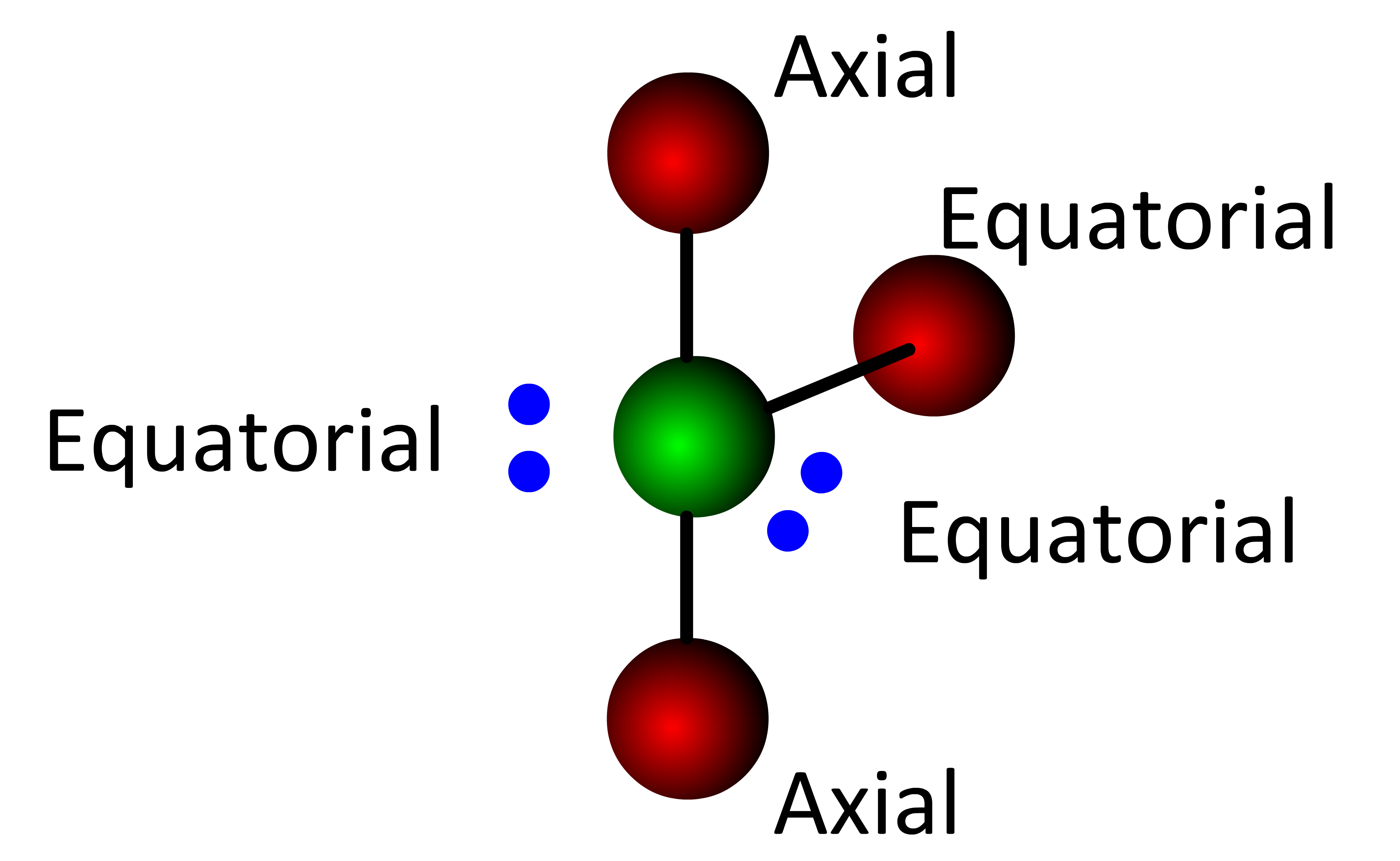 . . . . . this forms the T-Shaped molecular geometry.
Finally, when a third lone electron pair is placed in the last equatorial position, the resulting molecular geometry is linear.
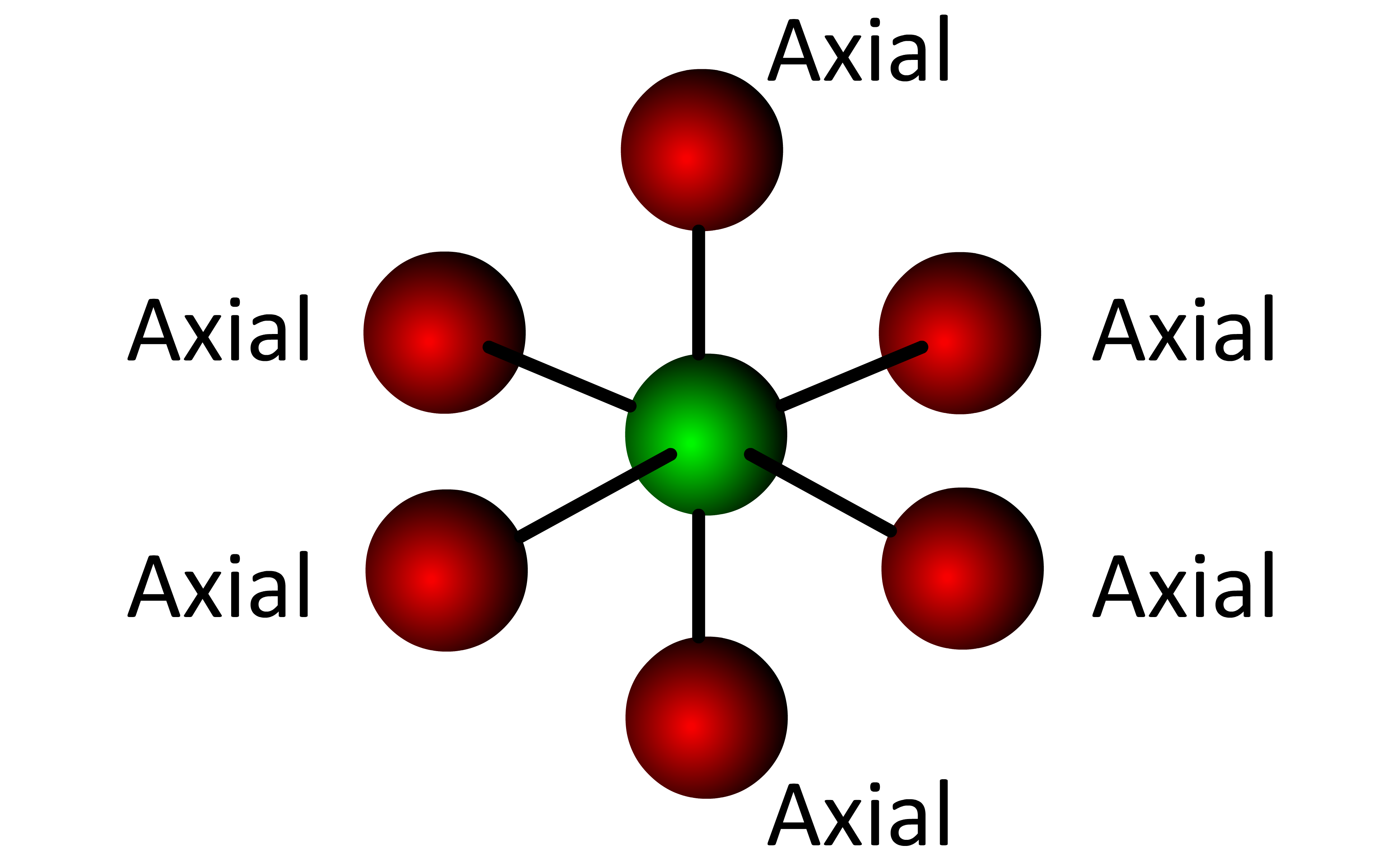
Every position in the octahedral molecular geometry is an axial position and all angles are 90° or 180°. When the Lewis structure of a molecule with an octahedral electronic geometry shows a lone electron pair on the central atom (:BrF5), the electron pair can be placed in any position  . . . . . this forms the Square pyramidal molecular geometry.
As soon as the first electron pair is placed on the octahedral structure, four of the regions (∠ 90°) become equatorial to the electron pair and one region (∠ 180°) becomes axial to the electron pair. When the Lewis structure of a molecule with an octahedral electronic geometry has two lone electron pairs on the central atom (XeF4), the second electron pair must be placed in the 180° axial position 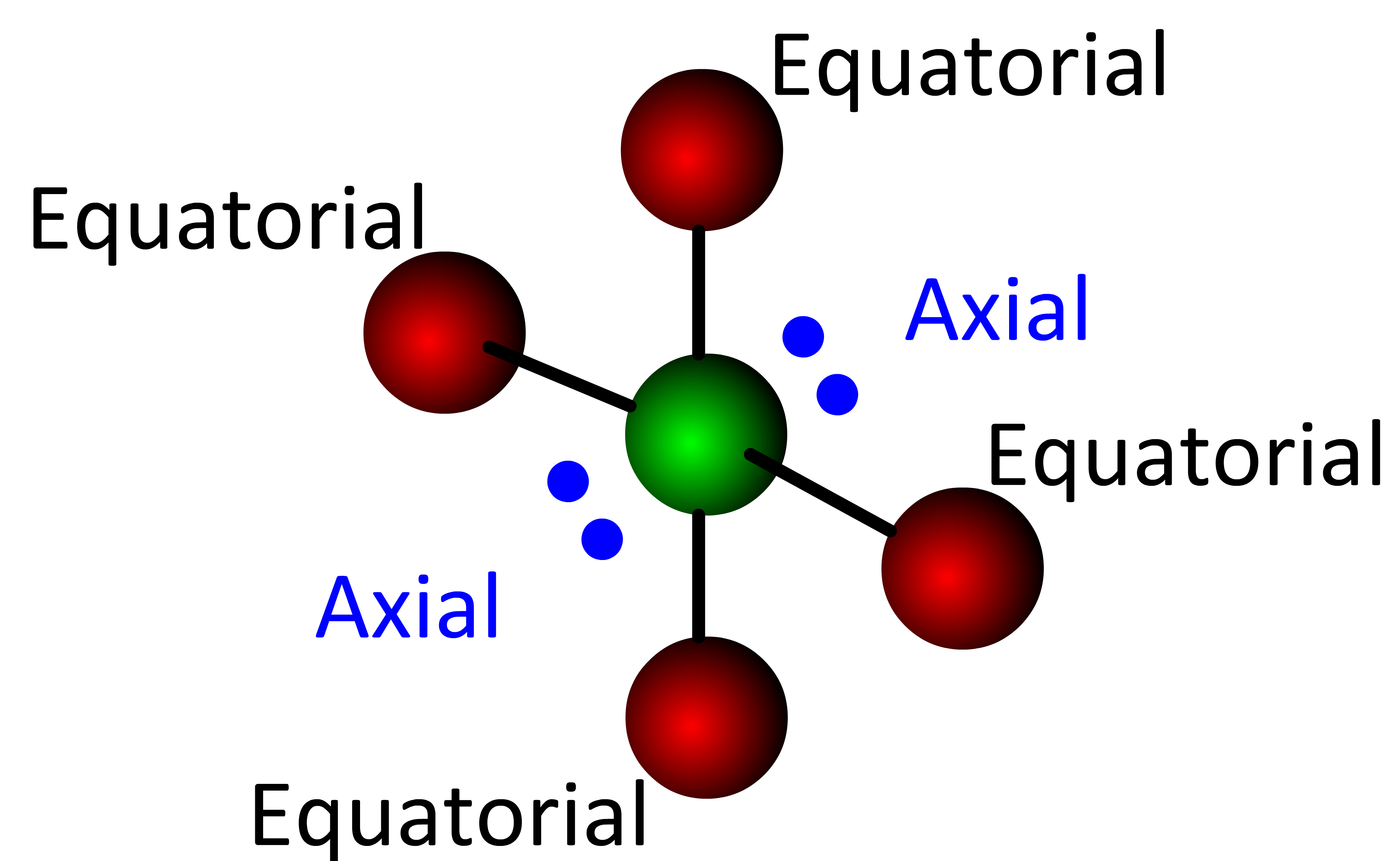 . . . . . this forms the Square planar molecular geometry.
Activity: click the molecules below to show the electron-containing orbitals.
Click the molecule a second time to show its molecular geometry. Several form pyramidal structures and one (SF4) has an "animated" molecular geometry (the real structure is not animated, but the animation helps to remember the name).
Activity: determine the molecular geometry for the central atom in the following molecules. Note that while all atoms have an electronic geometry, only atoms bonded to two or more atoms (i.e. a central atom) can have a molecular geometry.
Once you have written down an answer, click Show Answer to check your answer.
|
Show Answer |
Show Answer |
Show Answer |
Show Answer |
Show Answer |
Show Answer |
3D Rotation - JMol Viewer
Activity: touch/drag or click/drag the molecules below to rotate in 3D. The molecules are displayed using 3Dmol Viewer created by Nicholas Rego and David Koes . . . .3Dmol.js: molecular visualization with WebGL . . . . Bioinformatics (2015) 31 (8): 1322-1324 doi:10.1093/bioinformatics/btu829
Acetylene, H–C≡C–H |
Carbonate ion, CO32- |
Carbon tetrachloride, CCl4 |
Phosphorus pentachloride, PCl5 |
Sulfur hexafluoride, SF6 |
Bond Polarity
Introduced in Section 7.2, polar covalent bonds connect two nonmetals of differing electronegativities. A polar covalent bond has a δ+ pole and a δ– pole creating a bond moment (a vector possessing both direction and magnitude). A quantitative approach reveals both the direction and magnitude of the bond moment where the magnitude (μ) is the product of the total charge (Q) and the distance separating the δ+ and δ– charges . . . . μ = Qr. However, for the moment we will take a qualitative approach where only the direction of the bond moment is considered. Recall that electronegativity increases from left to right (→) and bottom to top (↑) in the Periodic Table with Fluorine being the most electronegative element. In a C–F bond, the Carbon is δ+ and the Fluorine is δ–. Instead of writing something like . . . .
Cδ+—Fδ–
to show the polarity of a polar covalent bond, we use a "vector-like" symbol ( ) where the "+" part of this symbol is positioned above the more electropositive element and the arrow points toward the more electronegative element.
C—F
Activity: determine the direction of the bond moment in the following bonds. Use the Periodic Table to assist in determining the most electronegative element. Once you have an answer, click Show Answer to check your work. |

|
|||
H—Br
Show Answer |
O—C
Show Answer |
N—O
Show Answer |
Be—Cl
Show Answer |
|
F—B
Show Answer |
O
S Show Answer |
N
C Show Answer |
N—Cl
Show Answer |
|

Polarity of Molecules
As described above, bond moments are vector quantities that have both a magnitude and direction. The addition of all the bond moments in a molecule will show the direction and magnitude of the molecule's dipole moment and reveal any δ+ and a δ– regions in the molecule. A molecule with a dipole moment is polar and will have δ+ and δ– regions. In a quantitative approach, the dipole moment is determined by "adding" the individual bond moment vectors where the tail of Vector 2 is placed at the head of Vector 1 while maintaining the magnitude and direction of each vector. Continue the "head to tail" placement until all the vectors have been used. A "resultant vector" drawn from the tail of Vector 1 to the head of the last vector shows the magnitude and direction of the molecule's dipole moment.
Activity: mouseover the molecules below to show the direction and relative magnitude of the individual bond moments. Then, click the molecules to show the "head-to-tail" addition of bond moments. Note that molecules 1, 2, 3 and 5 have been drawn so that all bonds are in the plane of the computer screen, while molecule 4 has a bond behind () and a bond in front of () the computer screen. In addition, Molecule 4 has a C–F bond moment whose magnitude is greater than the C–Cl bond moment . . . . this gives the molecule an overall dipole moment and makes it polar.
In practice, a qualitative approach is used that gives the direction of the dipole moment, but not its magnitude. In the Activity above, the direction of the dipole in Molecule 4 can be determined by imagining a bond moment for C–F that is "larger" (a qualitative term) than the C–Cl bond moment since Fluorine is more electronegative than Chlorine. If the molecule were CCl4, then all the bond moments would cancel out . . . . the fact that the C–F bond moment is "larger" provides the information needed to accurately predict the direction of the dipole moment is.
Activity: use the bond moments and molecular geometries of the molecules below to help determine their polarity. If polar, determine the direction of the dipole moment.
Once you have written down an answer, click Show Answer to check your answer.
|
Show Answer |
Show Answer |
Show Answer |
Show Answer |
Show Answer |

Show Answer |
Polar molecules are affected by an electric field and adopt an orientation where the δ+ region of the molecule orients toward the negative plate and the δ– region toward the positive plate. This property of polar molecules explains why polar solvents dissolve polar solutes . . . . the δ+ region of the solvent is attracted to the δ– region of the solute (and vice versa). In fact, a common solubility expression is "like dissolves like" which is covered in Chapter 11 - Solutions.
Activity: observe the effect of a charged balloon on a stream of water a very polar molecule.
- Click/drag the balloon to the boy's sweater and rub the sweater several times to transfer electrons.
- Drag/drop the balloon on the right side of the interactive.
- Click/rotate the stopcock to the open position.
- Click/drag the balloon toward the stream of water exiting the buret - what happens?
- Click the Play button and answer the three questions listed in the interactive.
- Click a radio button to select your answer.
- Click the Check Answer icon to grade your answer.